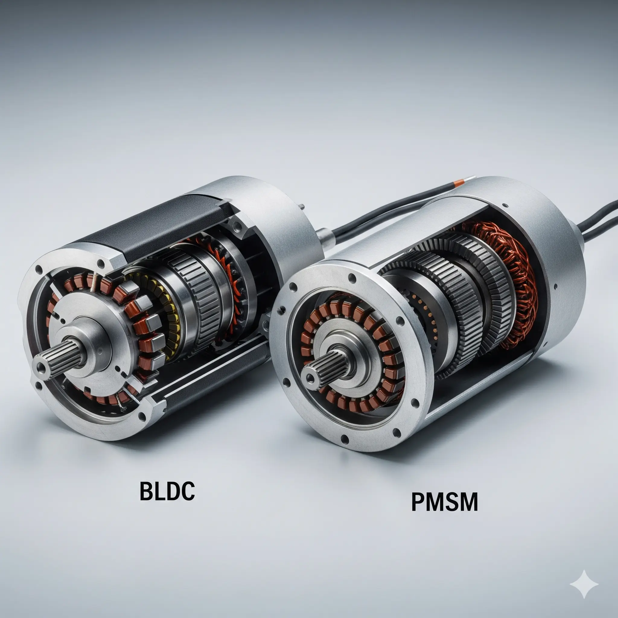
Navigating the world of brushless motors can be confusing. While brushless DC (BLDC) and permanent magnet synchronous motors (PMSM) are both brushless, they are not the same. Understanding their key differences is crucial for selecting the right motor for your application.
The core distinction lies in their design and how they are controlled.
1. Back EMF: The Fundamental Difference
The most important difference between these two motor types is the shape of their Back Electromotive Force (BEMF). This is the voltage generated by the motor as it rotates.
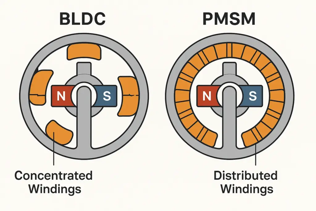
- BLDC Motors are designed to have a trapezoidal BEMF waveform. This shape is created by a magnetic field that is nearly uniform across each pole.
- PMSM Motors are designed to have a sinusoidal BEMF waveform. This is achieved through a more complex magnetic field design that varies smoothly across each pole.
This single difference dictates the type of control, performance, and optimal use case for each motor.
2. Control Strategy: Simple vs. Precise
The BEMF waveform directly determines the most effective way to drive the motor.
- BLDC Control: Because of its trapezoidal BEMF, a BLDC motor is most efficiently controlled with trapezoidal (or six-step) commutation. The controller switches the current to the motor’s phases in a simple, step-by-step sequence. This control method is easy to implement and cost-effective, but it can lead to higher torque ripple and noise.
- PMSM Control: The sinusoidal BEMF of a PMSM motor is best controlled using Field-Oriented Control (FOC). This advanced method uses complex algorithms to continuously adjust the current in a smooth sine wave. FOC delivers extremely smooth torque, high efficiency, and quiet operation, but it requires a more powerful microprocessor and a high-resolution position sensor.
3. Performance and Applications
While both motors are excellent for a wide range of tasks, their distinct characteristics make them better suited for different applications.
- BLDC Motors: Their simple control and high torque density make them a great choice for cost-sensitive applications where high performance is not the absolute priority. They are often found in:
- Power tools
- Home appliances
- RC vehicles and drones
- Computer fans
- PMSM Motors: Their smooth torque, high efficiency, and precise control are ideal for high-performance and high-precision applications. They are commonly used in:
- Robotics and automation
- Electric vehicles (EVs)
- Industrial pumps and compressors
- Medical equipment
Conclusion
In summary, the choice between a BLDC and a PMSM motor depends on your specific needs. If you require simple, cost-effective, and robust performance, a BLDC motor is likely the best choice. If your application demands exceptional smoothness, high efficiency, and precision, a PMSM motor is the superior solution.
Leave a Reply